|
|
|
|
 Sharing the Load between PSU's in a system Sharing the Load between PSU's in a system
|
|
Date Posted: May 1 2003
|
|
Author: Yo-Duh_87
|
|
|
|
|
Posting Type: Article
|
|
Category: Electronics
|
|
Page: 1 of 2
|
|
Article Rank:No Rank Yet
Must Log In to Rank This Article
|
|
|
|
|
Note: This is a legacy article, imported from old code. Due to this some items on the page may not function as expected. Links, Colors, and some images may not be set correctly.
|
|
|
Sharing the Load between PSU's in a system By: Yo-Duh_87
|
|
|
|
|
Sharing a load between multiple PSUs
By: Yo-Duh_87 5/1/03
( was really wrote months earlier )
|
|
|
I know that many of you have computers with 400 W or greater PSUs (Power Supply Unit), I have one myself (Antec TruePower 430). These tend not to run cheap, and often cost up to $100 for a good one (the prices go up higher, but I don't even consider paying that much for a PSU). If you are running a TEC, or other power hungry device, you might even already have 2 (or more!) PSUs. In this article, I'm going to explain a new method of distributing the power between multiple supplies. It does not cost much per supply, and requires no modification to the actual supply. It also boasts the benefits of having a minimal voltage drop, and not allowing the PSUs to damage each other through the other PSUs attempting to bring the others up to their voltage (the charging effect). Before I begin, I would like to apologize for the poor picture quality. My digital camera has a tendency to dislike taking photos of anything close up, so it took a little trickery to make the pictures look good (between a little situating, and a good bit of photo editing!).
|
|
|
|
|
|
|
How it all works
|
|
|
I have been working on a project that utilizes a lot of power, approximately 34 A at 12v, about 400 W! That is a lot of power!! Mind you, this is not computer related at all, so you TEC junkies can stop drooling ;)
I had looked into multiple methods of supplying this power; building my own supply, buying a supply that had that much power (yeah, right!), but they all were too costly.
So, I thought that I'd buy 2 (or more) computer PSUs, and hook them together. I bought 2 400w PSUs from bilsystem.com, for $17 apiece, just to experiment with. They only have around 11 A on the 12v line, but it was just for an experiment.
|
|
 |
|
|
My dad (who is an Electronics Engineer) and I were talking about how I was going to attach the two supplies together, and my dad came up with a brilliant idea: mosfets. At first, I was skeptical, but as he explained it more, it started to make sense.
Mosfets are semi-conductors, basically a complex block of silicon. There are two major types of mosfets, P-channel, and N-channel. We will be using N-channel mosfets in this circuit, as they are more efficient than their P-Channel counterparts. The intent of this article is not to explain how mosfets work, but you can find more info here.
|
|
 |
|
|
|
Let me explain the schematic (or circuit diagram, whatever you want to call it). The ICs on the board are Analog Devices ad1193 FET drivers (U1 and U2); these connect to the gate of the N-Channel mosfet (International Rectifier IRF 1407, M1 and M2). The 15V zener diode (D1 and D2) is just protection, to make the circuit a little safer.
The FET drivers take in 12v, and turn it into 18v at a very low current, saturating the mosfet gates beyond the VGS barrier (Vs + 4). This lets the mosfet act like a very low ohm resistor, and restricts the current very little. It may produce a little heat, but it is not much (your sound card will more than likely put out more heat than this will ;) ).
The trademark of this circuit, one of the things that sets it apart is the use of the mosfets positive temperature coefficient. It sounds complex, but the concept is simple. As the load draws current through the mosfets, they get hot, therefore increasing the resistance. The other mosfet(s) connected to the other supplies will therefore be a lower resistance, encouraging the current to flow through them causing the load to be shifted more evenly between the different supplies.
In comparison to other methods, the numbers would say that it is quite superior. Below is a list of various methods I have found people to use.
|
|
|
Method:
|
Credit:
|
Pros:
|
Cons:
|
|
Diodes connected in series with the supplies
|
No known source
|
Prevents the supplies from attempting to charge each other, easy.
|
You can lose up to .6 volts using this method, pushing your power well below the ATX spec. Also, by losing .6v, you're dissipating a lot of heat depending on how much current you are drawing.
|
|
Resistors connecting the supplies
|
Procooling's own OnDaEdg, the article can be found here.
|
OnDa experienced a voltage increase, which I find unusual, it is also easy.
|
Possibility of the supplies attempting to charge the other one resulting in some serious trouble. The resistor might also create heat.
|
|
Mosfet circuit connecting supplies
|
My dad and I ;)
|
Minimal voltage drop (less than 0.2 V in most cases, mosfet resistance is 0.0078 ohms), no possibility of the supplies attempting to charge each other. It also shares the power so that both supplies share the load equally.
|
Circuit requires moderate-soldering skills, costs more than the other methods, and may produce a small amount of heat (not much, in my experience).
|
|
|
|
|
I have tried to be fair in my analysis of these various methods, but having both the low voltage drop and protection against the supplies attempting to charge each other decided it for me.
This method could be used in various ways. It can be used to hook two or more supplies together (the sky is the limit, as long as you buy a set of parts for each PSU), it can be made into a cheap redundant PSU by constructing a coupling circuit for each voltage line, or you could even use it to make a nice bench supply. As previously mentioned, I intended on using it for a special project, one that has nothing to do with computers.
|
|
Component list (where x equals the number of supplies you are going to be using):
|
|
|
|
|
Quantity
|
Description
|
Digikey part number
|
Digikey Price*
|
|
x
|
FET driver
|
LTC1154CN8-ND
|
$3.25
|
|
x
|
MOSFET (currently out of stock, you may use the IRL1104 instead, with slightly decreased performance)
|
IRF1407-ND
|
$2.60
|
|
x
|
15v Zener diode
|
1N4744AMSCT-ND
|
$0.25
|
|
x
|
Heatsink (just a precaution)
|
Hs279-ND
|
$0.30
|
|
Varies
|
Molex connectors (I just took mine off a bunch of spare junk I had lying around)
|
Varies
|
Varies
|
|
|
* (as of time of writing, USD)
|
|
|
|
I ordered all these parts off Digikey, but they are available from other suppliers. I ordered more than enough, to allow for further expansion and human error (also, so that I would not have to pay the $5 handling fee for orders under $20!!).
I chose to solder this circuit, as I don't feel like spending $80 to have a PCB made, and also don't feel like buying all the acid and other materials needed for a custom etch.
|
|
|
|
Now, I don't have any pictures of the in-progress building, but I do have a few hints:
- Put all the components on the board first, and secure them with only 1-2 pins.
- Start wiring one portion, flowing from top to bottom, take your time.
- Finish the other portions.
- Use a knife/razor blade/etc. to cut where you might have a solder bridge. I did this between all my IC and mosfet traces, to avoid shorts (just to be cautions).
- I didn't do this, but you can use epoxy or hot glue to seal the bottom of the circuit board, to prevent shorts.
The number one thing is to enjoy yourself, and not to rush the entire thing. If you're in a hurry, you are likely to mess things up, and that is not good ;)
|
|
|
|
|
|
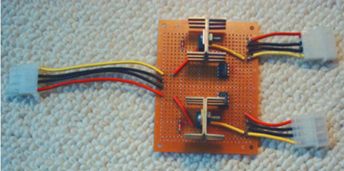
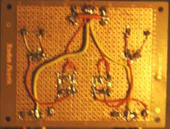
For those of you wondering how I soldered this thing up, here is a blurry picture of my extremely messy solder job.
|
|
|
 |
|
|
Again, I do apologize for the picture quality; my Digital Camera has no clue what the word "focus" means ;)
|
|
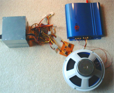
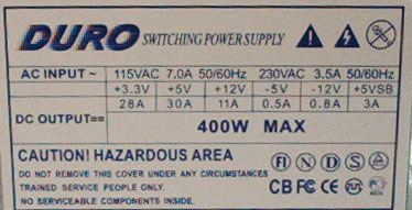
I tested with various loads, and returned interesting results. I had expected something like this, but it was gratifying to see it all work. Below are the results. For the testing, I used the two el-cheapo generic "Duro" brand PSUs, purchased from bilsystem, along with various devices that I "liberated" from various sources.
|
|
|
|
|
Load:
|
Single PSU
|
Dual PSU with circuit
|
|
none
|
11.73
|
11.72
|
|
Antec fan
|
11.66
|
11.66
|
|
400 W Car amplifier at full volume (as the PSUs and stereo would allow)
|
10.5-11 (music was way distorted, couldn't make much out)
|
11-11.5 (varies with the music)
|
|
|
|
|
Note: Your mileage may vary. The two supplies that were used are quite weak and are a little lack luster as far as the 12v rail, but you get what you pay for!
|
|
|
|
| Random Forum Pic |
 |
| From Thread: Easy waterblock but good perfomance |
|
| | ProCooling Poll: |
| So why the hell not? |
|
I agree!
|
 67% 67%
|
|
What?
|
 17% 17%
|
|
Hell NO!
|
 0% 0%
|
|
Worst Poll Ever.
|
 17% 17%
|
Total Votes:18Please Login to Vote!
|
|