|
|
|
|
 External diode readings from Socket 939 CPUs External diode readings from Socket 939 CPUs
|
|
Date Posted: May 16 2005
|
|
Author: pHaestus
|
|
|
|
|
Posting Type: Article
|
|
Category: Electronics
|
|
Page: 1 of 1
|
|
Article Rank:No Rank Yet
Must Log In to Rank This Article
|
|
|
|
|
Note: This is a legacy article, imported from old code. Due to this some items on the page may not function as expected. Links, Colors, and some images may not be set correctly.
|
|
|
External diode readings from Socket 939 CPUs By: pHaestus
|
|
|
|
|
External diode readings from Socket 939 CPUs
By: Derek Peak (pHaestus)Â Â Â Â Â Â Â 5/16/05
|
|
|
I've spent a lot of time and effort testing Socket A waterblocks for Procooling. One of the biggest reasons these test results have been useful was the modification done to my Socket A CPU to generate calibrated and higher resolution temperatures for testing. It's clear that the era of Socket A is now past, and the Procooling testbed is due for a much-needed makeover. I decided to replace the well-used 8K3A/1700+ TBredB test system with a new AMD Socket 939-based system and a Winchester 3000+ CPU. A quick scan of the AMD spec sheets suggested that the same technique used for pulling diode readings to a MAX6655 EVSYS should work with the new 939 pin CPUs. In fact, in some ways this modification is simpler on the 939 chips because the pins are at the edge of the processor. However, in other, more accurate ways this modification was a huge pain in the ass. Perhaps other people who are thinking about doing something like this can learn from some of my mistakes as they are detailed below. And I suspect everyone (almost) will be happy to see Procooling return to water cooling reviews with a more modern setup.
|
|
|
|
|
|
|
|
As I mentioned in the introduction, AMD's technical document for the AMD64 CPU makes this sound like a really straightforward exercise. The diode pins for the socket 939 CPU are located at AJ1 (THERMDC) and AJ2 (THERMDA). This is on one of the CPU's corners, and the pins are on an outside row too. In principle one can just bend those pins out, solder on them, cut a hole in the socket top for the wires to pass through, and call it a day. In practice I ran into several problems that I'd like to mention. First of all, I could not find an easy way documented on the web to take the top piece of a socket 939 socket off the motherboard. This meant that there was no easy way to make an incision for the wires to exit the socket. I eventually settled on a highly sophisticated solution: I heated a knife blade with a cigarette lighter and used the hot blade to cut trenches in the socket where I wanted the wires to go. This worked surprisingly well.
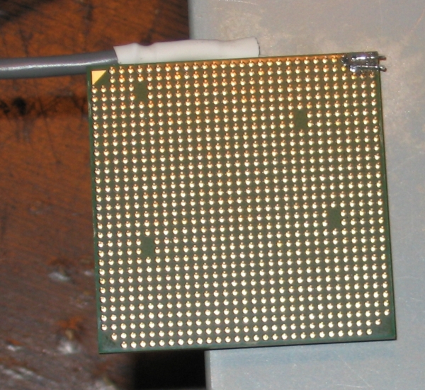
With space for wires, I could start soldering the leads for the MAX6655 to the CPU. Here is where I ran into the REAL problem: The pins of 939 chips are much smaller than those of Socket A CPUs and they are far more fragile. One can't just bend them down, solder wires upon them, and expect they will remain in position. I accidentally ripped one of the pins off the CPU while learning this fact. The workaround to this problem is to desolder the pins from the solder pads on the bottom of the CPU and then try to solder the wires directly to the solder pads. This actually worked quite well, but it led to another problem.Â
|
|
 |
|
|
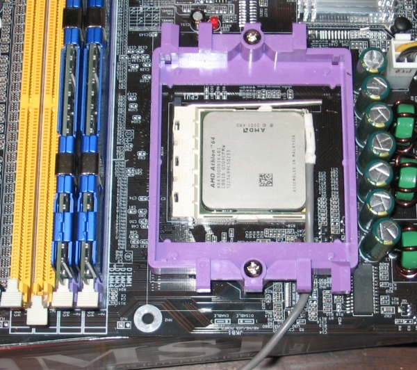
I first soldered up the diode reader with CAT5 cable, and the temperature reading of the CPU was fine in open air or in the socket with the ZIF lever up, but as soon as I locked it in place with the ZIF lever the temperature would change by as much as 20C. The wires were somehow making contact with the socket's wiring when the CPU was locked into place. My solution to this problem was to solder the CPU pins to a bit of wrapping wire (30 gauge single stranded wire) and then connect those patch wires to my shielded cable. Once this was done, I superglued the finished wiring to the side of the CPU casing so that the wires could not twist or be strained as the CPU is moved around. THIS IS VERY IMPORTANT; otherwise you'll rip the wiring off of the CPU during either the calibration or normal use.
|
|
 |
|
|
You can see that I have all the wires neatly heatshrinked to protect them and that the shielded cable for the diode reader is tucked under the Socket 939 retention mechanism. This stops any strain from making it to the soldered diode points on the CPU if the system has to be moved around. Although I ran into a few problems when putting this together, I am very pleased with the final product. I also would like to mention that John "Hoot" Hill (a regular contributer at Overclockers.com) actually told me in advance that (a) you have to remove the pins to connect a diode reader and (b) you should use 30 gauge wire for the connection. He was exactly right.
|
|
You might be thinking to yourself "That's pretty cool and all, but why bother with this? Can't you just read CPU temperatures from MBM or Speedfan or something without all this effort?" 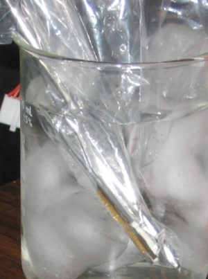 The answer is that yes, you can. But you have no idea whether the temperature that you are reading has any real bearing on the CPU's actual temperature. There are plenty of examples of problems with using onboard readings. It is known that CPU temperature sometimes can change drastically when you flash your motherboard's BIOS. It is also known that different manufacturers having drastically different CPU temperatures for the same chip. This procedure eliminates all those problems because we are now reading the temperature directly from the diode with a high quality external unit. There is another advantage to soldering up an external reader: We can calibrate it versus a known high accuracy thermometer. The answer is that yes, you can. But you have no idea whether the temperature that you are reading has any real bearing on the CPU's actual temperature. There are plenty of examples of problems with using onboard readings. It is known that CPU temperature sometimes can change drastically when you flash your motherboard's BIOS. It is also known that different manufacturers having drastically different CPU temperatures for the same chip. This procedure eliminates all those problems because we are now reading the temperature directly from the diode with a high quality external unit. There is another advantage to soldering up an external reader: We can calibrate it versus a known high accuracy thermometer.
The traditional method of calibrating a temperature probe is to use a water bath and a second probe of much greater accuracy. One can then construct a calibration curve of "probe 1 temp" vs. "probe 2 temp", fit an equation to this curve, and adjust their measurements accordingly. For my calibration, I am using the same Digitec 5810 thermometer and YSI 702 probe used in all other calibrations. I have compared results of this unit to my new Fluke 2190 thermometer with 3 wire platinum RTD and the difference was less than 0.05C.
|
|
You can see a picture of both the CPU and the YSI probe in a ziplock bag inside ice water. My procedure was to allow the CPU and thermistor to equilibrate first with ice water and then collect diode readings while the water was stable to within the resolution of the Digitec (0.01C). Then I would add hot water to the beaker, allow it to come to a new steady state, and measure again. 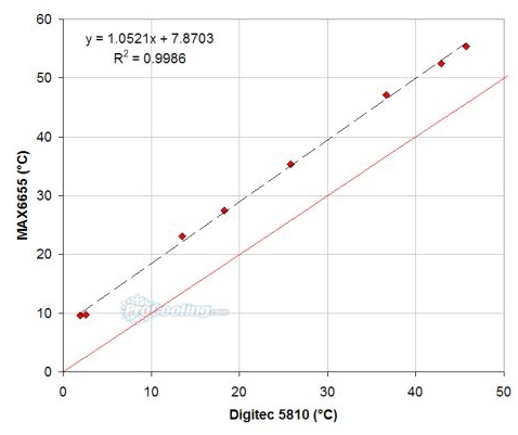 You can see that the relationship between the diode reading and the Digitec was quite linear from 1.5C to 45C. However, the diode reads much higher than the Digitec. I never had a deviation of more than 0.5C with the Athlon XP CPUs. I suspect that this is because the correction factor for the 939 diode may be different than the Socket A, and that it may respond a little differently to the differential pulse of my MAX6655 than it does to a motherboard's circuitry. This does perhaps lend some credence to claims that "motherboard x reads 10C too high" though; if the manufacturer used the same circuitry as with their Socket A boards without modification, it WOULD read around 8-10C higher than the true temperature if this CPU is representative of all Winchester cores. You can see that the relationship between the diode reading and the Digitec was quite linear from 1.5C to 45C. However, the diode reads much higher than the Digitec. I never had a deviation of more than 0.5C with the Athlon XP CPUs. I suspect that this is because the correction factor for the 939 diode may be different than the Socket A, and that it may respond a little differently to the differential pulse of my MAX6655 than it does to a motherboard's circuitry. This does perhaps lend some credence to claims that "motherboard x reads 10C too high" though; if the manufacturer used the same circuitry as with their Socket A boards without modification, it WOULD read around 8-10C higher than the true temperature if this CPU is representative of all Winchester cores. |
|
|
|
|
|
|
|
Here is the part that you guys probably are interested in: some testing results from the calibrated diode reader. I am running the following system:
- Soltek KT800 Pro motherboard
- 512MB (2x256) HyperX PC3200 RAM
- 30GB IBM 7200 rpm drive
- ATI 9600XT
- AMD64 3000+ (CBBID 0509) Winchester core
- Stock HS/Fan
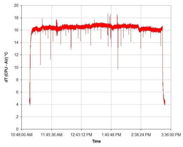
All testing was done at stock CPU speed (1.8GHz) and voltage (1.4V). The first test that I ran was a long Prime 95 run (every FFT size from 1024 down):
|
|
 |
|
|
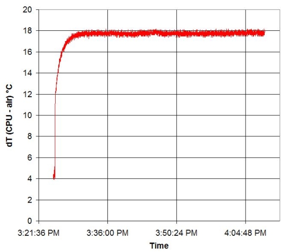
You can see the changes in FFT size as Prime95 runs; the size of the FFT affects the CPU temperature. This is pretty much identical to my previous results with the Socket A chip. However, there are some rather ominous-looking dips and spikes in the temperature as well that I've never observed before. I was pretty concerned about this and figured it was a problem with the diode reader until I ran CPUBurn (K7Burn high priority) to compare:
|
|
 |
|
|
These results look much cleaner and are similar to test results on the Socket A chips. So the single point spikes and dips in temperature for Prime95 are apparently a real phenomenon. It also looks like they are fairly regularly spaced. Perhaps the temperature drops are when each new FFT starts within a test, and then the larger temperature deviations are due to changes in FFT size. I am not sure why this would be more dramatic on the AMD64 compared to a TBredB. Could it be that the onboard memory controller has something to do with it? I suppose that regardless of the reason, the take home message is that CPUBurn is a much better CPU loading program for cooler testing.
|
|
This article was written to provide some tips on how to do this diode modification for socket 939 and to let everyone know that the new test setup is more or less running. We'll be using this new system to test complete cooling kits for Socket 939 very soon.Â
I want to close this article by saying that, for most readers, this modification is a really bad idea. The BIOS will not read a diode temperature afterwards (unconnected diode will always read -128C) so PWM fan control will no longer work. You run the risk of overheating your system because there's no thermal throttling or protection if the diode is always reporting such a ridiculously low temperature.
If you DO decide to copy this method, drop me a line and let me know if you observe similarly high temperatures for the diode during calibration and if you also see the spikes and dips in memory-intensive applications.Â
|
|
If you have any comments or Questions please email me at pHaestus@ProCooling.com
|
|
|
|
| Random Forum Pic |
 |
| From Thread: Post your watercooled pictures |
|
| | ProCooling Poll: |
| So why the hell not? |
|
I agree!
|
 67% 67%
|
|
What?
|
 17% 17%
|
|
Hell NO!
|
 0% 0%
|
|
Worst Poll Ever.
|
 17% 17%
|
Total Votes:18Please Login to Vote!
|
|


 External diode readings from Socket 939 CPUs


 The answer is that yes, you can. But you have no idea whether the temperature that you are reading has any real bearing on the CPU's actual temperature. There are plenty of examples of problems with using onboard readings. It is known that CPU temperature sometimes can change drastically when you flash your motherboard's BIOS. It is also known that different manufacturers having drastically different CPU temperatures for the same chip. This procedure eliminates all those problems because we are now reading the temperature directly from the diode with a high quality external unit. There is another advantage to soldering up an external reader: We can calibrate it versus a known high accuracy thermometer.
 You can see that the relationship between the diode reading and the Digitec was quite linear from 1.5C to 45C. However, the diode reads much higher than the Digitec. I never had a deviation of more than 0.5C with the Athlon XP CPUs. I suspect that this is because the correction factor for the 939 diode may be different than the Socket A, and that it may respond a little differently to the differential pulse of my MAX6655 than it does to a motherboard's circuitry. This does perhaps lend some credence to claims that "motherboard x reads 10C too high" though; if the manufacturer used the same circuitry as with their Socket A boards without modification, it WOULD read around 8-10C higher than the true temperature if this CPU is representative of all Winchester cores.
