|
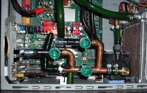
The layman might say "neat piping" or "looks sophisticated", but those familiar with how pumps actually work will say "What have you done to that pump inlet?" Pumps in general, and centrifugal pumps in particular, should not be throttled on the suction (intake) side. Ever. I am not trying to single out one person here; I have seen many people using 90 degree barbed fittings on their pump intakes and/or 90 degree fittings throughout their loops. And just to put those people in good company, also lump everyone that reduces the inlet of their pump with hose barbs in the same category. Let's look at a bit of theory and explain why this is a bad (awful) idea.
Sources of head loss in cooling loops
I am not an engineer, and my technical training in fluid mechanics is pretty limited. I rely mostly on a very useful and practical book: Crane Technical Paper 410 "Flow of Fluids through valves, fittings, and pipes" (http://www.cranevalve.com/tech.htm ). The following equations and numbers are taken from there, and I highly recommend picking up a copy if you find the following discussion interesting.
As a starting point, consider what happens at the molecular level when a pump moves water through a pipe. The pump exerts work on the water to generate flow, and some of this energy will be wasted by the generation of friction. This friction may come in the form of water molecules colliding with one another, or it may be friction of water with the walls of pipe. The consequence of these frictional forces is a drop in pressure in the same direction as the fluid flow. The terms head loss and pressure drop are used interchangeably to describe this loss in pressure across a length of pipe. The Darcy equation defines this mathematically as:
hL = f(L/D)v2/2g
where hL is the velocity head, f is the friction factor (which may be found in tables or determined experimentally), L/D is the ratio of pipe length to internal diameter, v is velocity of flow and g is the acceleration of gravity. This equation is fairly intuitive; for fluid velocity to increase, so to must the head loss. To maintain high water velocity in restrictive pipes, pressure (aka hydraulic head) must be increased.
For fittings and valves, one is no longer simply considering the length of a straight pipe. Instead, bends and restrictions also affect the head loss. The above equation now requires a modification:
hL =K v2/2g
where K is the resistance coefficient, which is defined as the number of velocity heads lost due to the valve or fitting. If desired, one can relate this resistance coefficient to equivalent pipe length by using the Darcy equation:
K = f(L/D)
where f is the friction factor and L and D are the length and diameter of the pipe, in feet.
Since head losses are additive, it is theoretically possible to estimate the total head loss of a cooling loop provided that estimates for friction factors are available for all tubing and fittings and that data exists for the water block and radiator of choice. For our purposes, however, examining the tabulated K coefficient values in Crane 410 should be sufficient.
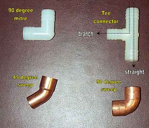
Let's take a look at some commonly used fittings in water cooling loops, a 90 degree mitre connector (aka barbed 90, a 90 degree copper sweep, a 45 degree copper sweep)2 of which make a 90 degree turn, and a T connector.
|


 Maximizing flow rates in H2O setups


