|
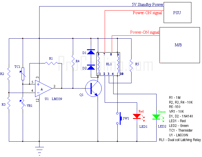
TC1 is the Thermister that will be located on the CPU itself. Once the circuit has been constructed, it is small enough to easily fit inside of the PSU itself if you so wish.
You may have noticed the two LEDs. The red LED is an indicator that the High-Temp threshold has been exceeded and will stay until the temperature has come down below the threshold and the reset switch has been pressed. Any time the temperature is below the threshold, the Green LED will be lit.
Here is a basic description of what is happening here:
U1 is a basic comparator. Basically, it will change its output 'state' depending on the two inputs and their voltage levels relative to each other. R2 and R3 are used to setup a reference voltage across the (-) input. The (+) input will vary in voltage depending on the temperature of the Thermister (Higher temps mean higher voltage on (+) input). As the temperature of the Thermister rises, the (+) input voltage will eventually exceed the (-) input at some point. When this happens, the output goes 'high' which allows the base of Q1 to be driven ON. (for the electronic geeks, the output is a open collector design). When Q1 is switched on, one side of the relay is powered on. This side of the relay latches the 'Power-ON' signal to position in which it is no longer passed on to the motherboard. Now, even if the temperature of the Thermister falls below the threshold, the latching relay will hold itself in this state regardless of what happens to Q1. So, if your CPU tried to nuke itself while you are away, you will come back to find your system shutdown. It will NOT keep trying to reboot.
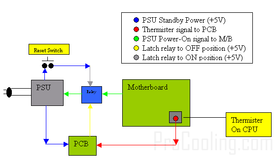
For the truly astute readers, you may have wondered how this little circuit keeps going after the system has shutdown. If you have, good job. The answer is, the circuit is taking advantage of the +5V Standby power which is supplied with ATX PSU. This +5V is ALWAYS on regardless of whether the computer is turned on or not. The only time it's off is when the PSU is actually unplugged from the wall.
In order to reset the relay once the 'problem' is fixed and the Thermister temperature has fallen below the threshold, the momentary switch SW1 will need to be pressed. Doing this momentarily completes a circuit through the other side of the latching relay and once again allows the 'Power-ON' signal to reach the motherboard. In both these instances, the corresponding LED will be lit to indicate which state the relay is currently in. Simple, huh?
So by now your screaming at the monitor …'Enough of the geek talk!! How the heck do I actually build the friggin thing?!' Well, don't get yourself in a tizzy. We'll get to that shortly.
|


 Build your own CPU Overheat sensor/shutdown device

