|
|
|
|
 Reading from the Athlons on-die thermal diode Reading from the Athlons on-die thermal diode
|
|
Date Posted: May 22 2002
|
|
Author: pHaestus
|
|
|
|
|
Posting Type: Article
|
|
Category: Hardware Modding
|
|
Page: 1 of 2
|
|
Article Rank:No Rank Yet
Must Log In to Rank This Article
|
|
|
|
|
Note: This is a legacy article, imported from old code. Due to this some items on the page may not function as expected. Links, Colors, and some images may not be set correctly.
|
|
|
Reading from the Athlons on-die thermal diode By: pHaestus
|
|
In January, I wrote an article about making your own AMD diode reader using a Maxim 6657 IC and a few dollars in parts. I got the original idea from a friend of mine (Peter North). I expected for Peter to write an article on the construction of the Maxim ICs, but he never has published it anywhere. Since I get bombarded with e-mails daily on the construction of these devices, I am going to go ahead and explain this now along with some details on using them for testing cooling gear. Reports are starting to trickle in of motherboards that can read from the internal diode (Epox 8K3A and Asus A7V333 reportedly do this), but many users have older boards and would like to add diode support.
|
|
|
|
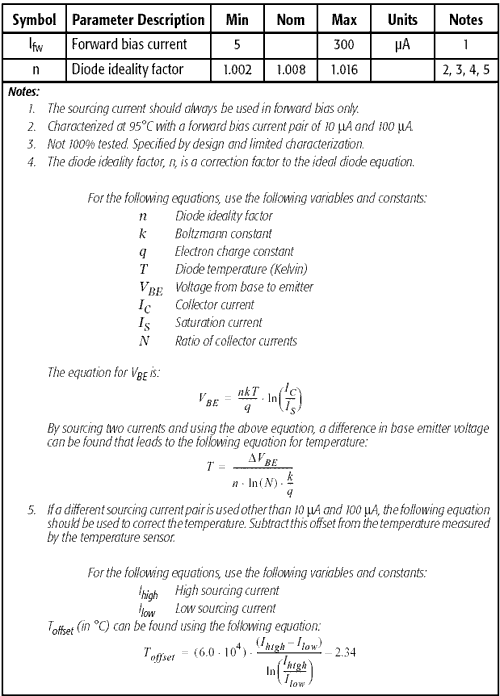
I should start off with some background reading on AMD's internal diode and recommended testing methods. Basic characteristics of the AMD internal diode (present on Athlon MP, XP, and 1.0GHz and higher "Morgan" Durons) can be found in section 7.14 of AMD tech doc #24309: AMD Athlon XP processor Model 6 data sheet (http://www.amd.com/us-en/assets/content_type/white_papers_and_tech_docs/24309.pdf). If you prefer, you can also look in the AMD Duron Processor Model 7 data sheet (section 7.13). The table listing the characteristics of the Palomino core embedded diode are identical in both documents, and are reproduced below:
|
|
 |
|
Other required reading for the serious Socket A cooling geek should include:
AMD tech doc #24228: Methodologies for measuring temperature on AMD Athlon and Duron processors (http://www.amd.com/us-en/assets/content_type/white_papers_and_tech_docs/24228.pdf). This document from AMD details the use of several evaluation kits from Maxim and Analog that can be used to read internal diodes of Palomino core CPUs.
|
|
|
|
I thought that many might also appreciate a little more information about SMBus and some of the possibilities that it has for PC modifications. SMBus-based diode readers were my first real interest into the SMBus and how it works, and it is probably unfamiliar to many of you as well. First of all, SMBus is an abbreviation for System Management Bus, and it was developed by Intel in 1995. SMBus is a serial interface that is 100% compatible with the older I2C bus that it replaced. Accordingly, you will sometimes see items that are referred to as I2C rather than SMBus-based. The SMBus interface is designed so that external ICs (such as the MAX6657 we are using) can interface with the computer and monitor hardware health. Temperatures and voltages are most commonly monitored, but LCDs are also available that connect via SMBus and it is possible to add PWM fan control (or temperature-based fan control with commonly available ICs for SMBus. Some motherboards (notably Asus and Abit) have headers that make interfacing with SMBus trivial.
|
|
|
|
|
|
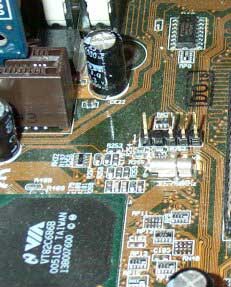
Even if your motherboard does not have a header, you can still access SMBus. All motherboards use SMBus to communicate with DIMMs, and so it is possible to access SMB_Data and SMB_Clock (the two SMBus wires that are relevant for our reader) by soldering either onto a DIMM or (more conveniently) onto the backside of the motherboard on the pins of the DIMM. For DDRAM, pins 91 and 92 are SMB_Data and SMB_Clock, respectively. For SDRAM, pins 82 and 83 are are SMB_Data and SMB_Clock, respectively. If you hack into the signal this way, you will also need to add wires for 5V and ground to your reader; the SMBus header provides these as well.
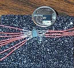
Now that you know a little more about SMBus, it is time to choose an IC that is the heart of a diode reader. The Maxim 6657 is a good choice for monitoring AMD diode temperatures for several reasons. First of all is its accuracy (+/-1C) and resolution (0.125C), and second is the fact that it uses voltages of 10 and 100 mA for sourcing, which are identical to the specifications for the Palomino diode (so no temperature offset calculations are necessary). The last advantage of the 6657 is its large size compared to the rest of the Maxim family. This makes soldering wires to the 6657's legs much simpler than its QSOP brethren. The only drawback to the MAX6657 is that its address is hardwired, so it isn't possible to use multiple MAX6657s in one computer.
|
|
|
|
|
|
Some of the other QSOP Maxim thermal monitoring ICs are also quite interesting if you can handle the soldering. If you need more temperature probes, then you might consider using a MAX6655 (two remotes) or a 1668 (4 remotes but with 3C accuracy). Many of the Maxim ICs are also capable of sharing the SMBus as long as you assign them different addresses. This allows one to construct elaborate temperature monitoring setups over the SMBus, with up to 15 temps (12 remotes and 3 local) being possible with 3 MAX1668 ICs for example. As I mentioned earlier though soldering QSOP isn't the easiest thing you will do.
Notice the jumper that is there for scale. This will probably take a few tries .
|
|
|
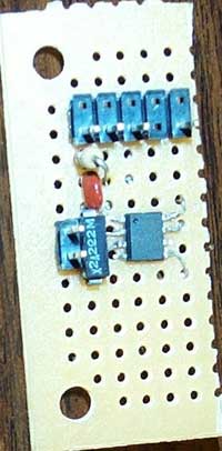
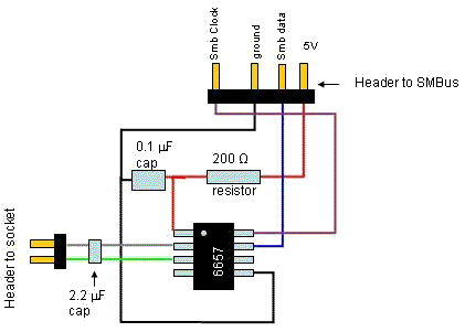
I bet that you are expecting a lengthy treatise with step by step instructions. I am sorry to disappoint you, but the whole trick is to follow the specifications on the Maxim data sheet http://pdfserv.maxim-ic.com/arpdf/MAX6657-MAX6659.pdf (RTFM? A novel concept!). There is a typical circuit that is identical to the diode readers that Peter and I have constructed. Since some people aren't familiar with schematics, I will post a cartoon that illustrates what goes where:
|
|
 |
|
I can give you a few tips on assembly that might prove useful. First of all, it is important to connect the wires to the legs of the IC without shorting the legs to adjacent ones. When you are wiring up QSOP this becomes particularly challenging. The easiest way to repair this (trust me you WILL do it) is to use a piece of wire that is formed into a hook. Just warm the wire and use it to dig the solder out of the legs. This turns out to be a very useful trick. The other thing that will be helpful is
|
|
|
|
|
to find some very fine wire for soldering onto the legs. I use 30 gauge wire (called wrapping wire) with good success.
Once you have assembled a diode reader, then the last remaining thing to do is to solder wires from pins S-7 and U-7 of the CPU socket to the DXN and DXP of the diode reader.
|
|
|
 |
|
|
I use a 2pin header so I can move the diode reader from system to system easily.
Once the diode reader is wired to the SMBus header (or hardwired to the motherboard) and connected to the socket pins then it is time to fire up your computer and open some temperature monitoring software. Motherboard Monitor5 detects the diode reader as MAX1617, but reports temperatures from it properly. Speedfan 4.05 beta properly detects the reader as a MAX6657.
|
|
One thing that no one who is using the diode readers has seemed to spend much time with is verifying that they actually work properly. There are some (relatively) simple tests that really are needed to make sure that all is well with the diode monitoring setup.
|
|
|
Importance of proper design
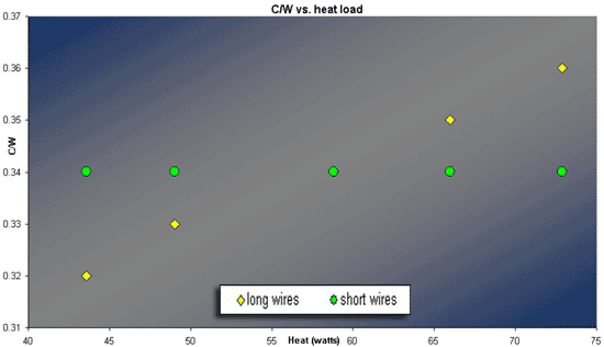
This might seem trivial, but following the Maxim specifications is really crucial for getting reliable results. For example, the choice and length of wire is actually one of the most important considerations of the whole process. The AMD internal diode works via measuring a voltage differential in the microamp range, so resistance along the wires becomes a serious problem. Maxim discusses this at some length in their technical document, but perhaps not enough attention has been paid to this fact. If you construct calibrations of C/W vs. heat load, you can easily see that having wires longer than the Maxim recommendation (4" vs. 8" in my test) results in a non-linearity of the diode readings.
|
|
|
 |
|
|
|
|
Be very careful in testing your diode reader over a range of heat load to verify linearity. This is a problem that will otherwise invalidate all of your testing. To calculate C/W, use a program like radiate (or else the AMD technical document for your CPU) to estimate the heat load at several different CPU clock speeds. Then measure the intake air temperature (Tamb) and the CPU diode temperature (Tdie).
C/W = (Tdie-Tamb)/W
This should remain constant over a full range of clock speeds. The calculation of C/W is not particularly accurate (I have heard it referred to as a "hack term" with respect to its use by the overclocking community) but in this case it proves quite useful.
|
|
|
|
Other Potential Issues
There is a lot of care taken (in the AMD technical document and in the Maxim pdf) to try and minimize line noise. The primary symptom of this will be numbers that jump around when the diode reader or the leads going to the socket are moved. The ways to minimize this are to place a 2200pF capacitor across DXN and DXP and to use a third wire that is twisted along with the leads and soldered to ground at the reader. I personally haven't noticed any fluctuations like this with my readers, but it is nonetheless important to follow spec. One source of wildly fluctuating temperatures I have observed came from poorly soldered joints at the socket. Make sure that you get a good joint or you will have problems with the results from the reader.
Another important consideration is supplying clean voltage. Maxim goes to some length in their circuit to make sure that the 5V input is clean. This in theory shouldn't be much of a problem if you are tapping into the voltage via the SMBus (the motherboard should regulate voltage), but we all know about fluctuation problems with the 5V line and AMD systems. The addition of a 200 ohm resistor and capacitor (as spec) should solve these potential problems.
|
|
|
|
Using your New Diode Reader and Comparing Temps  |
|
|
|
|
| Random Forum Pic |
 |
| From Thread: Two pumps config - serial or paralell? |
|
| | ProCooling Poll: |
| So why the hell not? |
|
I agree!
|
 67% 67%
|
|
What?
|
 17% 17%
|
|
Hell NO!
|
 0% 0%
|
|
Worst Poll Ever.
|
 17% 17%
|
Total Votes:18Please Login to Vote!
|
|


 Reading from the Athlons on-die thermal diode


