Login to ProCooling
Name: Pass:
Not Logged In.
Search:
ProCooling Technical Discussions
Overland Storage SnapOS v4 & Image File Links
kiwa 535 Day(s) ago.
/sadmin/debug.cgi
ozmatt 932 Day(s) ago.
Getting back into the water
ben333 1112 Day(s) ago.
ID This Waterblock.
jaydee 1595 Day(s) ago.
ProCooling Geek Bits
Happy 20 year on Procooling!
satanicoo 476 Day(s) ago.
Fluke 17B+ ... the multimeter I've always wanted b...
Noise 1901 Day(s) ago.
Ben's Win 98 box, redone! Build up
ben333 3556 Day(s) ago.
Project Black & Blue - Ben's new HTPC
ben333 3616 Day(s) ago.
Site News and Blogs
User Registrations kinda back open
Jag 1009 Day(s) ago.
New User Registrations are blocked
ben333 1132 Day(s) ago.
Where is Joe these days? JoeKelly.co
ben333 1423 Day(s) ago.
Stuff over the last few years, Blogs, etc...
rhkcommander 1806 Day(s) ago.
The Pro/Market
GTX 280 for US $308.11 !!!!!!
sam amaar 2279 Day(s) ago.
FS: Laptop hardware (CPUs, Memory, HDDs, Wifi, etc...
ben333 4418 Day(s) ago.
FS external watercooling units from jpiperformance...
Halo_Master 4456 Day(s) ago.
FS Snap Server 4200
abuthemagician 4581 Day(s) ago.
Build Build your own CPU Overheat sensor/shutdown device
Date Posted: May 24 2001
Author: CK42
Posting Type: Article
Category: Electronics
Page: 1 of 2
Article Rank:No Rank Yet
Must Log In to Rank This Article
Note: This is a legacy article, imported from old code. Due to this some items on the page may not function as expected. Links, Colors, and some images may not be set correctly.
Build your own CPU Overheat sensor/shutdown device By: CK42

CPU Over-Temp Detector / PSU Shutdown How 2

A ProCooling.com Guest article.
By: CK42

What Does It Do?
     This tutorial will show you how to build and install a circuit that will attempt power down your PSU when your CPU reaches a pre-specified temperature. After this occurs, a momentary switch will need to be depressed in order to reset the relay after the CPU temperature has reached levels below the triggering threshold.

Why Do This?
     The reason for this How-To stems from the increasing need for some type emergency system shutdown in the event that your prized CPU decides to nuke itself due either to your own frightening negligence or one of Murphy's favorite laws.

What Do I Need To Do This?
     First, you'll need patience…lot's of it.  You'll also need some ability to use a soldering iron, various sharp objects (check with your parental control units for permission) and an IQ slightly higher than that of the average bipedal invertebrate. 

OK.  How Do I Do It?
     Before you go and get overwhelmed with pictures and such, let's take a look at the schematic of this circuit and see how things should work.

Schematics:

**Important – This circuit requires the use of signals received and sent by an ATX PSU. If you have an AT PSU, this project will NOT work.**

Here's a mock over-temp scenario:

  • Computer is running when CPU exceeds temperature threshold set in the PCB circuit.
  • PCB circuit registers this condition via the Thermister.
  • PCB circuit sends a 5V signal to latching relay which in turn disconnects the 'Power-On' signal to the PSU.
  • PSU loses 'Power-On' signal which in turn then causes the PSU to shutdown power to the motherboard.

You discover the problem and fix it:

  • CPU temperature problem is corrected and CPU temperature falls below threshold.
  • PCB registers this condition via the Thermister and does nothing.
  • User depresses the Reset Switch.
  • Reset switch latches the relay to the other position.
  • Relay now allows the 'Power-On' signal to again reach the PSU.
  • PSU has 'Power-On' signal and re-applies power to the Motherboard.

And now here is the actual schematic for those of you either interested or who can actually read them.

Circuit Operation:

Q1 - MPS2222A

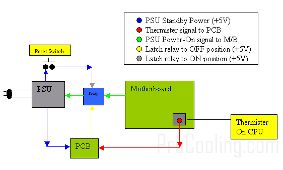
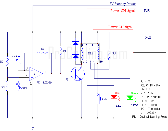
TC1 is the Thermister that will be located on the CPU itself.  Once the circuit has been constructed, it is small enough to easily fit inside of the PSU itself if you so wish.

You may have noticed the two LEDs. The red LED is an indicator that the High-Temp threshold has been exceeded and will stay until the temperature has come down below the threshold and the reset switch has been pressed. Any time the temperature is below the threshold, the Green LED will be lit.

Here is a basic description of what is happening here:

     U1 is a basic comparator. Basically, it will change its output 'state' depending on the two inputs and their voltage levels relative to each other. R2 and R3 are used to setup a reference voltage across the (-) input.  The (+) input will vary in voltage depending on the temperature of the Thermister (Higher temps mean higher voltage on (+) input). As the temperature of the Thermister rises, the (+) input voltage will eventually exceed the (-) input at some point. When this happens, the output goes 'high' which allows the base of Q1 to be driven ON. (for the electronic geeks, the output is a open collector design). When Q1 is switched on, one side of the relay is powered on. This side of the relay latches the 'Power-ON' signal to position in which it is no longer passed on to the motherboard. Now, even if the temperature of the Thermister falls below the threshold, the latching relay will hold itself in this state regardless of what happens to Q1. So, if your CPU tried to nuke itself while you are away, you will come back to find your system shutdown. It will NOT keep trying to reboot.

     For the truly astute readers, you may have wondered how this little circuit keeps going after the system has shutdown.  If you have, good job.  The answer is, the circuit is taking advantage of the +5V Standby power which is supplied with ATX PSU.  This +5V is ALWAYS on regardless of whether the computer is turned on or not. The only time it's off is when the PSU is actually unplugged from the wall.

     In order to reset the relay once the 'problem' is fixed and the Thermister temperature has fallen below the threshold, the momentary switch SW1 will need to be pressed.  Doing this momentarily completes a circuit through the other side of the latching relay and once again allows the 'Power-ON' signal to reach the motherboard. In both these instances, the corresponding LED will be lit to indicate which state the relay is currently in.  Simple, huh?

So by now your screaming at the monitor …'Enough of the geek talk!! How the heck do I actually build the friggin thing?!' Well, don't get yourself in a tizzy. We'll get to that shortly.

Construction of this lil Wonder Device

Random Forum Pic
Random Forum Pic
From Thread:
300w + 300w = 600w?
ProCooling Poll:
So why the hell not?
I agree! 67%
What? 17%
Hell NO! 0%
Worst Poll Ever. 17%
Total Votes:18
Please Login to Vote!


(C) ProCooling.com 2005 - All this glorious web geekness was brought to you by Joe's amateur web coding skills.
If we in some way offend you, insult you or your people, screw your mom, beat up your dad, or poop on your porch... we're sorry... we were probably really drunk...
Oh and dont steal our content bitches! Don't give us a reason to pee in your open car window this summer...