|
|
|
|
 AMD Thermal diode Calibration/Testing AMD Thermal diode Calibration/Testing
|
|
Date Posted: May 18 2003
|
|
Author: pHaestus
|
|
|
|
|
Posting Type: Article
|
|
Category: Hardware Modding
|
|
Page: 1 of 1
|
Article Rank: from 1 Readers
Must Log In to Rank This Article from 1 Readers
Must Log In to Rank This Article
|
|
|
|
|
Note: This is a legacy article, imported from old code. Due to this some items on the page may not function as expected. Links, Colors, and some images may not be set correctly.
|
|
|
AMD Thermal diode Calibration/Testing By: pHaestus
|
|
|
|
|
Fun with AMD diodes: CPU mutilation, calibration, and testing
By: Derek Peak (pHaestus) 5/18/03
|
|
|
This article has been a long time coming. And that is not to be taken lightly when said by a Procooling writer! It started over a year ago when I made my first AMD internal diode reader. One of the first questions in my mind (shortly followed by messages in my inbox) was "How can it be calibrated?" Not so easily, it turns out. Here's my story.
|
|
|
|
The traditional method of calibrating a temperature probe is to use a water bath and a second probe of much greater accuracy. One can then construct a calibration curve of "probe 1 temp" vs. "probe2 temp", fit an equation to this curve, and adjust their measurements accordingly. This is not at all straightforward when dealing with a diode reader that is soldered onto a motherboard and connects to the CPU diode via the ZIF socket. Every solder point in the system represents a possible source of resistance (and temperature compression). Another problem with my earlier diode readers was that they were located on the same system that was being tested under load. Some preliminary testing showed that CPU temperatures would rise as much as 5C when a second PC was used for collecting data. Apparently "100% load" is a rather arbitrary target. The final problem with the earlier homemade diode readers was their resolution. It is hard to do serious testing with a 1C resolution!
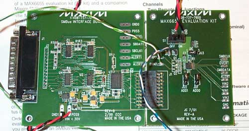
The problems with resolution and needing a second PC to collect the results were both solved by purchasing a Maxim 6655EVSYS diode evaluation system. The MAX6655 is actually two PCBs: a parallel port to SMBus adapter PCB (MAXSMBus) and a second diode/voltage reader built with the MAX6655 IC.
|
|
|
|
|
 |
|
|
|
|
The 6655 monitors 4 voltages (though I never wired it up for voltage) and reports three temperatures: one internal to the IC and two external diode probes. With the supplied software, I can achieve a 1/8C resolution with 1C accuracy out of the box. Calibrated vs. my Digitec 5810 dual linear thermistor, I was expecting to achieve accuracy of 0.1C (making the resolution more or less limiting). The Maxim software is technically only for Windows 95/98, but with DLPortIO (a free download) and a bit of fiddling with the parallel port's settings in device manager I got it working properly on my Windows XP notebook.
|
|
|
|
 |
|
So now we have resolution and a secondary testbed. All that's left is the calibration. Simple right? Well at least in theory…
|
|
|
|
|
|
There have been plenty of concerns voiced on the web about the linearity of AMD diodes (hi Nevin!), so calibration over the expected temperature range of interest is vital to obtaining meaningful results from my MAX6655. Resolution doesn't mean a damn thing if the numbers are not accurate, and so linearity must be proven and quantified. I thought long and hard about the best method of doing this, and arrived at the following procedure.
- Solder shielded wire onto the XP's diode pins directly
- Put the modified CPU into a water bath (inside Saran Wrap to protect it from water) and calibrate it
- Cut space in motherboard's socket for wires to fit rhrough
- Bask in the glow of a calibrated CPU diode
Thisstrategy was chosen because every solder point adds resistance, and so it is impossible to reliably calibrate the parts unless they are in the EXACT working conditions. This procedure ensures that, but Step 1 looks a little bit extreme.
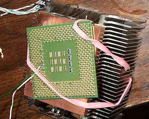
It turned out that it WAS pretty extreme in fact. To try and keep my CPU in good working condition, I used a rubber band to hold the core of the chip against a copper heatsink (Thermalright AX7). Then I flipped it so the pins were pointing up and ready for solder.
|
|
|
|
 |
|
|
|
I decided that this operation had more than a small chance of catastrophic failure, so I used a spare 1600+ XP. The first time I soldered it all together it worked well enough after adding the wires, but I didn't solder them in a position where it was convenient to route them under the socket. When I tried to install it into a motherboard, one of the wires came loose. When I tried to resolder the wire, two of the CPU's pins came off! One was the diode DXN pin, and I was unable to reattach it. The other pin was one of the CPU's VCC pins
Observation 1: Socket 462 CPUs still work fine with 460 pins as long as you happen to only misplace a VCC and a diode pin.
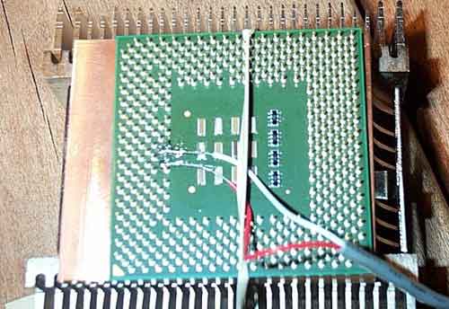
This put the calibration on hold for a while (obviously) and I moved on to other things for a while. I couldn't just drop this project altogether though; it kept bugging me that it wasn't completed. So one day I grabbed a beer, grabbed my soldering iron, and went after a second 1600+ that I found in my parts box. This time I remembered to orient the wires so they would pass through my socket hole and I also physically wrapped the wires around the pins to get a good mechanical contact before soldering.
|
|
 |
|
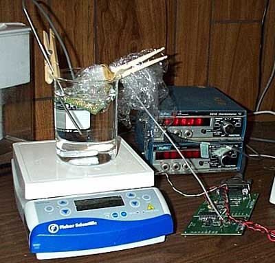
This worked much better. After this picture I wrapped the wires around one another again (as per Since87's advice) and then was ready to calibrate. For calibration, I decided to use a glass beaker and a magnetic stirrer/hot plate from my lab. I figured I could adjust the temperature of the water easily and keep it well mixed with this setup.
|
|
|
|
Observation 2: Magnetic stirrers generate interference that greatly affect the noise levels in diode readings
Observation 3: Hot plates don't work worth a damn for controlling temperatures in the 30-60C range with any precision.
|
|
|
|
The noise in the diode readings was the real killer. So instead of using the hot plate and stirrer, I opted for a Styrofoam container, ice, boiling water, tap water, and a wooden spoon for stirring it up. This isn't the ideal NIST-approved solution, but I could get approximately 15 diode readings while the water was stable to the resolution of my Digitec 5810 thermistor. Hot water was initially added, and readings were collected over time as the water cooled. Here is a graph comparing the diode temperature to the Digitec over a pretty wide range of temperatures:
|
|
|
|
|
|
Exceptional results in my opinion. Linearity verified, and calibration complete, I am now ready to actually set up a PC and do some testing.
Preliminary Testing
For the data collection and analysis I am using my IBM Thinkpad T30 notebook connected via parallel port to the MAX6655. For the test computer, I am using an Epox 8K7A+ (AMD761 chipset) motherboard with an AGKGA 1600+ (1400MHz at 10.5x133) Athlon XP processor. I used 1 stick of Kingmax PC2700 DDR set to "normal" speed in the bios, and set the CPU voltage to default (though MBM reported a Vcore of 1.79 rather than 1.75). Windows 98 SE was loaded on the system. The system is housed in a Lian Li PC-50 case on its side with the top and both side panels removed. As mentioned before, I cut away part of the CPU socket to allow for the diode wires to be routed outside of the case. I used the method detailed in this article, with the exception that I used a screwdriver to pop off the top piece of the socket rather than hacking at it while on the motherboard. A 6 inch (15cm) cd-rom audio cable was used as the wire connecting the diode of CPU to the MAX6655 kit. The MAX6655 was powered with a PSU separate from the test computer so that I could monitor temperatures at boot and after shutdown if needed.
|
|
 |
|
|
|
And in fact, showing a graph of temperatures as the PC goes through different functions seems a pretty good place to start. The graph below shows the temperatures reported by the MAX6655 internal diode (located inside the IC on the PCB), a transistor wired up in diode mode placed 1 inch above the center of the heatsink's fan to monitor intake air temp, and the reading from the CPU diode. The system was powered on and loaded windows, CPU HLT was enabled by setting register 62 to value B7 in WPCredit, and then the system was allowed to fully idle until temperatures were stable. Next, the system was put under load using CPUBurn high priority for a few minutes and then shut down by turning off the power. A few interesting observations can be made from this graph, some obvious and some more subtle. Starting at boot, there is a huge instantaneous temperature jump when the system POSTs. I was expecting the rise to be rapid, but not as large as can be seen. Once CPU HLT is enabled then the system predictably drops down to a relatively low temperature. Note though that even with the CPU in full idle that it is still several degrees over the heatsink's intake air. Moving right along, one can clearly see some spikes in temperature just before CPUBurn is started. Those spikes are due to moving the mouse, clicking on "My Computer" and navigating to the CPUBurn directory. As expected, the CPU gets hot when CPU Burn is running. What was not expected was the way that temperatures changed after power was shut off. Without power, the CPU immediately dropped in temperature, and then slowly (and linearly) continued to decrease over the next 35 minutes. One can think of a copper heatsink as a temperature buffer: it serves to make the temperature swing that a processor undergoes under use much smaller because the copper has a large capacity to absorb heat. However, when the system is turned off then this heat has to go somewhere. Some of the heat is radiated away from the heatsink, as can clearly be observed by the rise in air temperature above the heatsink. The other method of heat dissipation is back through the CPU core and pins to the motherboard's copper traces. Both of these processes are quite slow, so the system takes a long time to return to room temperature after powered down. Is this a problem? I don't think so. There are no spikes in CPU temperature after the system is shut down (how could there be?) so it is a non issue. A manufacturer or two does sell products to keep fans on after systems are shut down; I suppose because they made the same observation I am reporting. I found the rise in air temperature more interesting actually; the test system is open to the atmosphere, so presumably temps would rise somewhat higher in a closed case.
Another observation can be made from the graph that is probably of more interest to me than the rest of you. If you look at the noise level while the system is running (in the flat region of the CPU HLT command, for example) and after the PC was shut down, they have the same variability. This is a good thing ™ because it shows that there is not much electrical noise added to the readings by running the system.
Comparison of CPU loading programs
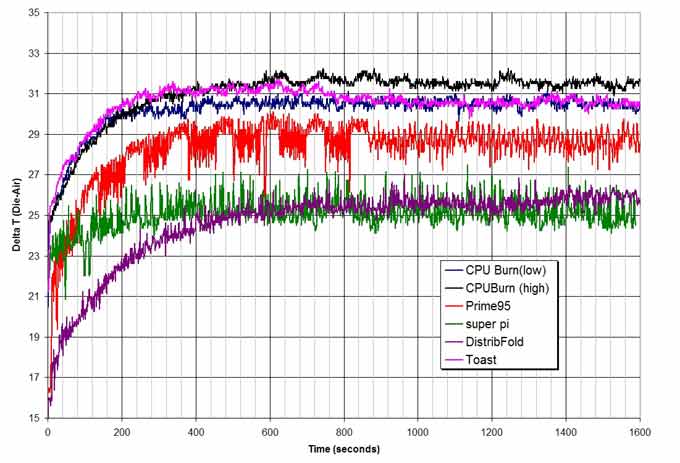
One question that has been nagging me for a long time is validity of programs that supposedly generate "100% CPU load". Sure they report this in the Windows task manager, but are they really equal? With my new-found resolution, I decided to find out. Intuitively, programs which access RAM often don't seem the wisest choice for comparative testing as they would (in theory) produce higher CPU temperatures if one has faster/more RAM. Programs which access the HDD are even worse choices because they involve the PC's IO system. If the goal is simply to generate heat, then having a memory or HDD bottleneck is counterproductive. I decided to take a look at some of the most popular methods of generating "100% CPU load" to see if any clear distinctions could be made.
The test programs that I used were:
All programs were run without shutting down the computer, moving any temperature probes, or making any changes at all to the test system. To (hopefully) account for variation in the room's temperature, the results are graphed as delta T, defined here as the difference between the CPU diode temperature and the air temperature one inch (25 mm) above the center of the CPU fan.
|
|
 |
|
|
There is a lot of information here in this graph, so let's take a bit of time to examine it carefully. First of all, there is a pretty large difference in how variable the temperatures are. CPUBurn and toast seem to run very tight code that keeps temperature swings under load to a minimum. Prime95, on the other hand, has huge temperature swings that are also a function of the size of the forward fourier transform that is being done (the large changes at the beginning of the run are the 1024k FFTs). Super Pi and Distributed Folding are somewhat in between, with some variation and regular oscillations in temperature. If one thinks about how these programs work then it makes sense I think. Toast and CPU Burn are just assembler code that throw CPU into a constant loop while super pi, prime95, and distributed folding clients have real work to be done (and verified) that requires interaction with the system RAM and HDD. I found the Prime95 results particularly interesting because of the changes in performance as the FFT size changed. I regraphed the Prime 95 results to more clearly show this:
|
|
|
 |
|
|
Whenever the CPU has to perform a FFT on data that is larger than its cache (256k for the XP), then it clearly has temperature swings. These oscillations are much smaller than when FFTs are being done on smaller file sizes. Even for the smaller sizes though there is a pretty large scatter of temperatures. This is not observed with CPUBurn or Toast, so I am concluding that it is an effect of the operations Prime95 is requesting from the CPU rather than an artifact due to electrical noise.
Another question that I have long been thinking about is the importance of FSB and ram timings in CPU temperature. I was pretty skeptical that this could really be observed with the testbed, but I decided to give it a go. My plan was to unlock the 1600+ so that I could dramatically change FSB. My unlocking job didn't work though so that test will have to wait for a later time. What I COULD still do was go into the bios and dramatically change RAM timings. So I used the "Turbo" settings for fast timings, and used "normal" settings for slow timings and manually set the CAS latency to 2.5 and turned off super bypass. I am calling this "slow timings".
|
|
|
 |
|
|
Ok so even I am a little surprised by the fact I can observe the difference. Remember, the MHz and FSB are identical and only ram timings are changed. I would expect that the difference in temperature using different FSBs and multipliers to achieve the same MHz would be even larger. How is it affecting the temperature exactly? Well one would presume that RAM accesses are the bottleneck and so as memory bandwidth increases then the CPU can do more work. This does not bode well for cross-comparison of temperatures between users using programs like Prime95, as it implies that RAM timings, FSB, and many other factors may affect the temperature. It also implies pretty strongly that a blanket estimate of "Watts" for C/W calculations is not very representative of real world conditions. The results also point to the use of a program like CPUBurn to load the CPU rather than one that is dependent upon other system components.
|
|
|
|
|
|
|
|
This test setup is already generating a large amount of interesting data, and I am currently developing a strategy to measure current and voltage that the CPU is pulling to avoid using a program like Radiate to estimate the watts of the processor. I am also currently working on cross-correlating the temperatures from this testbed with Bill Adams' Waterblock testing. Our goal in the short term is to try and get a reasonable estimate for the magnitude of secondary cooling effects that occur on real systems (cooling via transmission of heat to a motherboard's copper traces, loss of heat to air around the socket, etc). Hopefully I will have some even more interesting results to share with you all in a few weeks.
|
|
If you have any comments or Questions please email me at pHaestus@ProCooling.com
|
|
|
|
| Random Forum Pic |
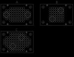 |
| From Thread: maximizing flow through a pin block |
|
| | ProCooling Poll: |
| So why the hell not? |
|
I agree!
|
 67% 67%
|
|
What?
|
 17% 17%
|
|
Hell NO!
|
 0% 0%
|
|
Worst Poll Ever.
|
 17% 17%
|
Total Votes:18Please Login to Vote!
|
|